Always developing vibration test systems
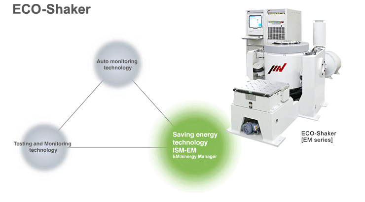
IMV's dynamic simulation systems have been developed with "intelligence" in mind and endeavour to support customers testing. The new Eco technology has been used in the IMV range.

Complicated settings are not needed.
Electricity consumption might be managed manually on electrodynamic systems, but this could be quite difficult for the system operator to optimise the consumption due to payload and test conditions. Our ECO-Shaker can achieve optimisation of power consumption refering to payload conditions.
You can confirm the result of reduction of CO2 and electricity consumption at glance.
By combination with IMV vibration controller ‘K2’ , ECO-shaker system will confirm real-time electricity consumption during testing. It was never available by conventional systems. Power consumption can be reported numerically after each test.
You can expect improvement of laboratory environment.
Noise to be expected from the conventional test system will give limitaion to installation place selection. Our ECO-Shaker can suppress the noise level by controlling the engine blower at optimised speed. Optimum control of the cooling system will reduce power consumption and noise level refering to test conditions.
We will contribute to well being of society from both sides of quality and environmentt
By Clean Development Mechanism (CDM) in January 2008 and revision of Rationalisation in Energy Use law in April 2009 were introduced in Japan, all enterprises have been obliged to be more energy efficient. ECO-Shaker promotes reduction of costs and CO? by saving electricity consumption, costs, and consequently contributes to society.
Real automatic energy saving driving
Complicated settings are not needed.
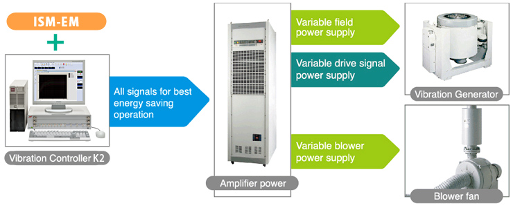
ECO-shaker is a electrodynamic vibration test system which automatically optimize output of power amplifier, power input to vibration and cooling blower rotation speed refering to payload and test conditions. So, complicated manual settings are not needed anymore. Since it is real automatic control according to working environment conditions, "drastic change in output levels due to change of test sample characteristics during the test", "temperature up in system caused by rising heat during operation" etc.. even if those phenomenon happen, it is possible to keep operation without stopping the test.

You can confirm reduction of CO2 and electricity consumption at real-time.
By combination with IMV vibration controller ‘K2’ , ECO-shaker system will confirm real-time electricity consumption during testing. It was never available by conventional systems. Power consumption can be reported numerically after each test, which clearly shown on monitor or display. So you can confirm the result at glance.

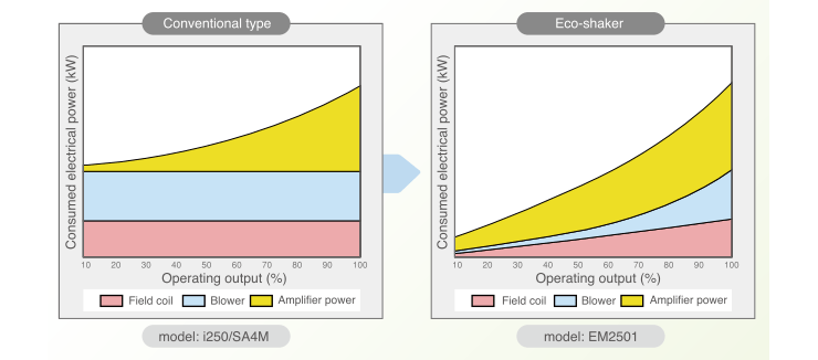
Comparison of electricity consumption with conventional shaker
The less system output, the more saving-energy you can expect.
Figures are calculated by comparing with conventional system of same sine force rating. Results may vary for system models, test conditions.


Operation of ISM-EM (Power consumption)
Power consumption on conventional vibration systems would require manual calculation refering to test conditions. ISM-EM technology of the ECO-Shaker can automatically control the output of the power amplifier, force generation of the shaker, and rotation speed of the cooling blower to achieve best efficiency refering to test conditions.

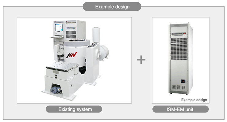
Correspondence to existing system [Retro fit]
Saving energy by ISM-EM technology can be applied on existing IMV vibration test systems by adding the ISM-EM unit and some calibrations. Contact us for further information and delivery.

|
System Model
|
EM2201
|
EM2301
|
EM2401
|
EM2501
|
EM2502
|
EM2551
|
EM2601
|
|
System
Specifications
|
Freq. Range(Hz)
|
0~3300
|
0~3000
|
0~2600
|
0~2500
|
0~2500
|
0~2600 *5)
|
0~2600 *5)
|
|
Rated
Force
|
SINE(kN)
|
8
|
16
|
24
|
32
|
40
|
49
|
54
|
|
RANDOM(kNrms)*2)
|
8
|
16
|
24
|
32
|
40
|
49
|
54
|
|
SHOCK(kN)
|
16
|
32
|
48
|
64
|
80
|
98
|
108
|
|
Max.
Acc.
|
SINE(m/s2)
|
1250
|
1250
|
1200
|
914
|
1142
|
907
|
1000
|
|
RANDOM(m/s2rms)
|
875
|
875
|
840
|
640
|
800
|
635
|
700
|
|
SHOCK (m/s2)
|
2500
|
2500
|
2400
|
1828
|
2284
|
1814
|
2000
|
|
Max.
Vel.
|
SINE(m/s)
|
2.2
|
2.2
|
2.2
|
2.2
|
2.2
|
2.2
|
2.2
|
|
SHOCK(m/s)
|
2.2
|
2.2
|
2.2
|
2.2
|
2.2
|
2.2
|
2.2
|
|
Max.
Dsp.
|
SINE(mmp-p)
|
51
|
51
|
51
|
51
|
51
|
51
|
51
|
|
Max. TRAVEL
(mmp-p)
|
60
|
64
|
68
|
68
|
68
|
64
|
64
|
|
Max. Load.(kg)
|
200
|
300
|
400
|
600
|
600
|
1000
|
1000
|
|
Power Requirements(kVA)*1)
|
16.4
|
26
|
36
|
51
|
57
|
80
|
83
|
Vibration
Generator |
Model
|
i220
|
i230
|
i240
|
i250
|
i250
|
i255
|
i260
|
|
Armature Mass(kg)
|
6.4
|
12.8
|
20
|
35
|
35
|
54
|
54
|
|
Armature Diameter(φmm)
|
190
|
200
|
290
|
440
|
440
|
446
|
446
|
|
Allowable eccentric moment
(N・m)
|
294
|
700
|
850
|
1550
|
1550
|
1550
|
1550
|
|
Dimensions(mm)W×H×D
|
1020x
903x
550
|
1124x
957x
860
|
1234x
997x
890
|
1463x
1187x
1100
|
1463x
1187x
1100
|
1527x
1196x
1100
|
1527x
1196x
1100
|
|
Mass(kg)
|
900
|
1500
|
2000
|
3000
|
3000
|
3500
|
3500
|
|
Power
Amplifier
|
Model
|
SA1M-
i20EM
|
SA2M-
i30EM
|
SA3M-
i40EM
|
SA4M-
i50EM
|
SA5M-
i50EM
|
SA7M-
i55EM
|
SA7M-
i60EM
|
|
Max. Output(kVA)
|
10
|
20
|
29
|
40
|
50
|
58
|
64
|
|
Dimensions(mm)W×H×D
|
580x
1750x
850
|
580x
1750x
850
|
580x
1750x
850
|
580x
1950x
850
|
580x
2100x
850
|
1160x
1950x
850
|
1160x
1950x
850
|
|
Mass(kg)
|
330
|
350
|
460
|
900
|
930
|
1400
|
1400
|
|
Controller
|
Vibration Controller
|
See Vibration Controller K2
|
| Cooling |
Cooling Method
|
Air cooling
|
|
Blower
|
Dimensions(mm)
W×H×D
|
492x
1128x
627
|
606x
1315x
844
|
707x
1531x
896
|
1057x
1841x
1078
|
1057x
1841x
1078
|
1328x
2140x
1033
|
1328x
2140x
1033
|
|
Mass(kg)
|
70
|
125
|
210
|
250
|
250
|
370
|
370
|
- *1) Power supply required is 3-phase 200/220/240/380/400/415/440V,50/60Hz. Voltage Down Transformer (Step-down transformer) is required for other voltage.
- *2) Rated force of RANDOM follow the ISO5344 standard. Please contact us for further information on RANDOM force conditions of each system.
- *3) Each value of specification indicates maximum power of the system. In the case of a long hours of test, it needs to be operated less than 70% of maximum power.
(The continuous use could be the cause of a premature failure.)
- *4) In the case of RANDOM durability test, please set the test definition of the peak value of acceleration waveform to be operated less than 1400 m/s2.
- *5) In the band of more than 2000Hz, excitation force pitches at the rate of -12dB/oct.
- *6) Frequency range values vary according to sensor and signal generator.
- *7) Mass and size can change in CE-support system.
Specifications (Large Displacement Type)
|
|
System Model
|
EM2305
|
EM2405
|
EM2505
|
EM2506
|
EM2555
|
EM2605
|
|
System
Specifications
|
Freq. Range(Hz)
|
0~3000
|
0~2400
|
0~2200
|
0~2200
|
0~2600 *5)
|
0~2600 *5)
|
|
Rated
Force
|
SINE(kN)
|
16
|
24
|
35
|
40
|
49
|
54
|
|
RANDOM(kNrms)*2)
|
16
|
24
|
35
|
40
|
49
|
54
|
|
SHOCK(kN)
|
40
|
55
|
70
|
80
|
98
|
108
|
|
Max.
Acc.
|
SINE(m/s2)
|
941
|
923
|
777
|
888
|
777
|
857
|
|
RANDOM(m/s2rms)
|
658
|
646
|
544
|
622
|
544
|
600
|
|
SHOCK (m/s2)
|
2352
|
2115
|
1555
|
1777
|
1555
|
1714
|
|
Max.
Vel.
|
SINE(m/s)
|
2.4
|
2.4
|
2.4
|
2.4
|
2.4
|
2.4
|
|
SHOCK(m/s)
|
2.4
|
2.4
|
2.4
|
2.4
|
2.4
|
2.4
|
|
Max.
Dsp.
|
SINE(mmp-p)
|
100
|
100
|
100
|
100
|
100
|
100
|
|
Max. TRAVEL(mmp-p)
|
120
|
120
|
120
|
120
|
116
|
116
|
|
Max. Load.(kg)
|
300
|
400
|
600
|
600
|
1000
|
1000
|
|
Power Requirements(kVA)*1)
|
28
|
38
|
53
|
57
|
82
|
86
|
|
Vibration
Generator
|
Model
|
J230
|
J240
|
J250
|
J250
|
J255
|
J260
|
|
Armature Mass(kg)
|
17
|
26
|
45
|
45
|
63
|
63
|
|
Armature Diameter(φmm)
|
200
|
290
|
440
|
440
|
446
|
446
|
|
Allowable eccentric moment
(N・m)
|
700
|
850
|
1550
|
1550
|
1550
|
1550
|
|
Dimensions(mm)W×H×D
|
1124x
1079x
850
|
1234x
1145x
890
|
1463x
1301x
1100
|
1463x
1301x
1100
|
1527x
1319x
1100
|
1527x
1319x
1100
|
|
Mass(kg)
|
1800
|
2400
|
3500
|
3500
|
4100
|
4100
|
|
Power
Amplifier
|
Model
|
SA3M-
J30EM
|
SA4M-
J40EM
|
SA5M-
J50EM
|
SA6M-
J50EM
|
SA7M-
J55EM
|
SA7M-
J60EM
|
|
Max. Output(kVA)
|
23
|
34
|
50
|
57
|
64
|
70
|
|
Dimensions(mm)W×H×D
|
580x
1750x
850
|
580x
1750x
850
|
580x
2100x
850
|
580x
2100x
850
|
1160x
1950x
850
|
1160x
1950x
850
|
|
Mass(kg)
|
380
|
490
|
930
|
960
|
1400
|
1400
|
|
Controller
|
Vibration Controller
|
See Vibration Controller K2
|
| Cooling |
Cooling Method
|
Air cooling
|
|
Blower
|
Dimensions(mm)
W×H×D
|
606x
1315x
844
|
707x
1531x
896
|
1057x
1841x
1078
|
1057x
1841x
1078
|
1328x
2140x
1033
|
1328x
2140x
1033
|
|
Mass(kg)
|
125
|
210
|
250
|
250
|
370
|
370
|
- *1) Power supply required is 3-phase 200/220/240/380/400/415/440V,50/60Hz. Voltage Down Transformer (Step-down transformer) is required for other voltage.
- *2) Rated force of RANDOM follow the ISO5344 standard. Please contact us for further information on RANDOM force conditions of each system.
- *3) Each value of specification indicates maximum power of the system. In the case of a long hours of test, it needs to be operated less than 70% of maximum power.
(The continuous use could be the cause of a premature failure.)
- *4) In the case of RANDOM durability test, please set the test definition of the peak value of acceleration waveform to be operated less than 1400 m/s2.
- *5) In the band of more than 2000Hz, excitation force pitches at the rate of -12dB/oct.
- *6) Frequency range values vary according to sensor and signal generator.
- *7) Mass and size can change in CE-support system.
Specifications (High Power Water Cooled Type)
|
|
System Model
|
EMK0301
|
EMK0621
|
EMK0622
|
EMK0801
|
EMK1251
|
EMK1252
|
EMK2001
|
EMK2002
|
|
System
Specifications
|
Freq. Range(Hz)
|
0~3000
|
0~2500
|
0~2500
|
0~2500
|
0~2500
|
0~2500
|
0~2000
|
0~2000
|
|
Rated
Force
|
SINE(kN)
|
30.8
|
49.0
|
61.7
|
80
|
100
|
125
|
160
|
200
|
|
RANDOM
(kNrms)*2)
|
21.5
|
49.0
|
61.7
|
80
|
100
|
125
|
160
|
200
|
|
SHOCK(kN)
|
61.6
|
98
|
123.4
|
160
|
200
|
250
|
320
|
400
|
|
Max.
Acc.
|
SINE(m/s2)
|
1000
|
1000
|
1000
|
1000
|
1000
|
1000
|
800
|
1000
|
|
RANDOM
(m/s2rms)
|
557
|
700
|
700
|
700
|
700
|
700
|
700
|
700
|
|
SHOCK (m/s2)
|
2000
|
2000
|
2000
|
2000
|
2000
|
2000
|
1600
|
2000
|
|
Max.
Vel.
|
SINE(m/s)
|
1.8*5)
|
2.0*5)
|
2.0*5)
|
2.0*5)
|
2.0*5)
|
2.0*5)
|
2.0*5)
|
2.0*5)
|
|
SHOCK(m/s)
|
1.8
|
2.0
|
2.0
|
2.0
|
2.0
|
2.0
|
2.4
|
2.4
|
|
Max.
Dsp.
|
SINE(mmp-p)
|
51
|
51
|
51
|
51
|
51
|
51
|
76.2
|
76.2
|
|
Max. TRAVEL
(mmp-p)
|
58
|
60
|
60
|
59
|
62
|
62
|
86
|
86
|
|
Max. Load.(kg)
|
500
|
1000
|
1000
|
1000
|
2000
|
2000
|
2000
|
2000
|
|
Power Requirements
(kVA)*1)
|
49
|
76
|
87
|
100
|
150
|
170
|
270
|
300
|
Vibration
Generatoer |
Model
|
K030
|
K060
|
K060
|
K080
|
K125
|
K125
|
K200
|
K200
|
|
Armature Mass(kg)
|
27
|
40
|
40
|
60
|
70
|
70
|
200
|
200
|
|
Armature Diameter(φmm)
|
320
|
400
|
400
|
446
|
560
|
560
|
650
|
650
|
|
Allowable eccentric moment
(N・m)
|
980
|
980
|
980
|
1550
|
2450
|
2450
|
4900
|
4900
|
|
Dimensions(mm)
W×H×D
|
1100x
1090x
824
|
1380x
1085x
1000
|
1380x
1085x
1000
|
1595x
1050x
1200
|
1776x
1360x
1300
|
1776x
1360x
1300
|
2465x
1908x
1740
|
2465x
1908x
1740
|
|
Mass(kg)
|
3000
|
3700
|
3700
|
5000
|
7000
|
7000
|
16000
|
16000
|
Power
Amplifier |
Model
|
EM4MM
-K30
|
EM6MM
-K60
|
EM8MM
-K60
|
EM14HM
-K80
|
EM18HM
-K125
|
EM22HM
-K125
|
EM26HM
-K200
|
EM32HM
-K200
|
|
Max. Output(kVA)
|
33
|
43
|
60
|
100
|
98
|
124
|
256
|
320
|
|
Dimensions(mm)
W×H×D
|
580x
1950x
850
|
1160x
1950x
850
|
1160x
1950x
850
|
1740x
1950x
850
|
1740x
1950x
850
|
2320x
1950x
850
|
2900x
1950x
850
|
3480x
1950x
850
|
|
Mass(kg)
|
950
|
1300
|
1350
|
2250
|
2400
|
3200
|
4000
|
4800
|
|
Controller
|
Vibration Controller
|
See Vibration Controller K2
|
| Cooling |
Cooling Method
|
Shaker:Water Cooling/Amp:Air Cooling
|
|
Primary Cooling Water Supply
(l/min)
|
195
|
260
|
260
|
390
|
390
|
390
|
520
|
520
|
|
Heat
Exchanger
|
Dimensions(mm)
W×H×D
|
580x
1700x
850
|
580x
1700x
850
|
580x
1700x
850
|
580x
1700x
850
|
580x
1700x
850
|
580x
1700x
850
|
950x
1900x
800
|
950x
1900x
800
|
|
Mass(kg)
|
400
|
400
|
400
|
400
|
400
|
400
|
600
|
600
|
- *1) Power supply required is 3-phase 200/220/240/380/400/415/440V,50/60Hz. Voltage Down Transformer (Step-down transformer) is required for other voltage.
- *2) Rated force of RANDOM follow the ISO5344 standard. Please contact us for further information on RANDOM force conditions of each system.
- *3) Each value of specification indicates maximum power of the system. In the case of a long hours of test, it needs to be operated less than 70% of maximum power.
(The continuous use could be the cause of a premature failure.)
- *4) In the case of RANDOM durability test, please set the test definition of the peak value of acceleration waveform to be operated less than 1400 m/s2.
- *5) If the tests (SWEEP or SPOT) need high velocity the maximum velocity value should be reduced to 1.4m/s.
In the case of continuous SINE test, at move than 1.4m/s, it may need optional cooling system, so please consult with us.
- *6) Frequency range values vary according to sensor and signal generator.
- *7) Mass and size can change in CE-support system.